
 English
 русский
 Español
 Português
 عربى


Fiber Connector Insertion Loss Factors: What Causes It and How to Control It
A technician once traced a link failure to a single patch panel pair: the connector was adding more than 3 dB of insertion loss — enough to eat half the optical power. The fiber was fine. The splices were fine. The connector itself was the problem. Fiber connector insertion loss factors are not mysterious, but they are many, and each one can silently consume part of your link budget. This article explains what causes insertion loss, the values you should accept, and the practical habits that keep connectors close to their ideal performance.
What Is Connector Insertion Loss and Why It Matters
Insertion loss (IL) is the optical power lost when light passes through a connector pair. It is measured in decibels, and it is unavoidable: every connection loses a little light to scattering, reflection, and imperfect coupling. What matters is how much is lost and why.
A link budget is finite. Consider a 20 km single-mode span at 1310 nm: fiber attenuation of 0.35 dB/km consumes 7 dB, two connector pairs add 0.6 dB, and two fusion splices add 0.2 dB, for a total of 7.8 dB. That leaves 2.2 dB of margin in a 10 dB system. Now let the connector pairs degrade to 0.6 dB each, and the total rises to 8.4 dB. The link still passes, but the margin has shrunk by 27 percent due only to connectors. In a longer span, or in a network with many patching points, the same degradation is what separates a stable network from a chronic problem.
The Main Factors Behind Fiber Connector Insertion Loss
All connector insertion loss comes from a small set of physical effects. If you understand them, you can diagnose a bad link and specify better components. The list below is ordered roughly by how often each factor shows up in field problems.
End face contamination
Contamination is the number one cause of excessive insertion loss in real networks. Dust, oil, and debris sitting between two mated end faces both scatters light and creates an air gap. A single 1 µm particle has been measured to add more than 1 dB of loss, and under high optical power the contamination can burn onto the glass and permanently damage the end face. This is also the cheapest factor to fix: most "bad" connectors become good again after inspection and cleaning.
Core alignment and lateral offset
The second major factor is lateral offset — the distance between the centers of the two fiber cores after mating. A lateral offset of just 1 µm can add roughly 0.2 to 0.4 dB in single-mode fiber, depending on wavelength and mode field diameter. Offset is created by ferrule hole eccentricity, imprecise connector keying, or an out-of-spec adapter. That is why connector, ferrule, and adapter must be treated as one alignment system.
Fiber Optic Adapter for Multiple Connector TypesThis adapter supports common connector formats like FC, SC, ST, LC, and MPO, and is part of the alignment system that controls lateral offset and insertion loss. Its specified return loss grades help ensure consistent performance in mated connections.View Product →
End face geometry and polish quality
The polished shape of the end face determines whether physical contact between the two fibers actually happens. Three parameters matter: radius of curvature, apex offset, and fiber undercut or protrusion. If the fiber is slightly recessed below the ferrule surface, an air gap remains at the interface and Fresnel reflection alone adds about 0.3 dB of loss, on top of scattered light. Factory-terminated components such as optical patch cords are produced under controlled polish conditions, which is why they deliver far more consistent insertion loss than field-polished connectors.
Mode field diameter mismatch
When two fibers have different mode field diameters, light couples inefficiently. This happens when a G.652 fiber is joined to a G.657 bend-insensitive fiber, or when patch cords from different manufacturers use fibers with slightly different geometry. The loss contribution is usually small — fractions of a decibel — but it accumulates when different fiber types are mixed across a link.
Ferrule and adapter tolerances
Ferrules are machined with inner hole tolerances of a fraction of a micron. An oversized hole lets the fiber sit off-center; a worn or loose adapter alignment sleeve lets the ferrules tilt or shift during mating. Array connectors such as MPO are especially sensitive because they align many fibers at once, so every fiber's position error adds into the total loss.
Mating cycles, cable strain, and environment
Every mating cycle wears the end face slightly. After hundreds of cycles, scratches and embedded contamination raise the loss of a connection that once measured well. Cable strain pulls on the connector body and changes mating force, while temperature cycling expands and contracts plastic and metal parts, shifting core position. A connector that passes acceptance tests on day one can fail later if the cable is routed under tension or the environment is harsh.
Typical Insertion Loss Values by Connector Type and Grade
Acceptance thresholds come from international standards such as IEC 61753-1 and TIA-568.3-D. In practice, a well-terminated single-mode connector pair should measure below 0.3 dB, and premium components reach 0.15 dB or less. When you select fiber optic patch cords, the connector type and polish grade define the loss you can expect and the return loss you can rely on.
| Connector | Typical IL (dB) | Maximum IL (dB) | Typical application |
|---|---|---|---|
| SC/UPC | 0.15 – 0.3 | 0.5 | Patch panels, FTTH |
| SC/APC | 0.15 – 0.3 | 0.5 | RFoG, PON access |
| LC/UPC | 0.15 – 0.3 | 0.5 | Data centers, switches |
| LC/APC | 0.15 – 0.3 | 0.5 | High-density FTTH |
| FC/UPC | 0.2 – 0.3 | 0.5 | Vibration-prone environments |
| MPO (12-fiber SM) | 0.3 – 0.6 | 0.75 | Parallel optics, breakouts |
Multimode connectors typically accept a slightly higher maximum, up to 0.5 dB for standard components, because the larger core relaxes some alignment demands but also increases the chance of offset loss relative to core size. Whatever grade you choose, evaluate connectors against the whole link budget, not a single pair.
How to Keep Connector Insertion Loss Under Control
Insertion loss is largely preventable at the design, installation, and maintenance stages. These practices consistently produce low loss in real networks:
- Inspect before you mate. Look at every end face with a fiber microscope. If it is not clean, use a dry click-clean pen first, then a wet-to-dry process for stubborn contamination.
- Never mix APC with UPC. The 8-degree angle of an APC end face is incompatible with a UPC end face; forcing them together damages both surfaces and raises loss and reflectance.
- Choose components rated for the application. A factory-terminated patch cord from a controlled production line delivers more consistent insertion loss than a field-polished connector.
- Keep dust caps on. Most contamination enters the network during storage and handling, not during operation.
- Protect the cable near the connector. Bending or pulling the cable changes the mating geometry and raises loss.
- Record baseline results. A baseline insertion loss for every span makes later degradation easy to detect.
 SC-SC Duplex Fiber Optic Patch CordFactory-terminated patch cords deliver more consistent insertion loss than field-polished connectors due to controlled polish conditions. This duplex SC-SC cord is suitable for applications requiring reliable low-loss connections in structured cabling or patch panels.View Product →
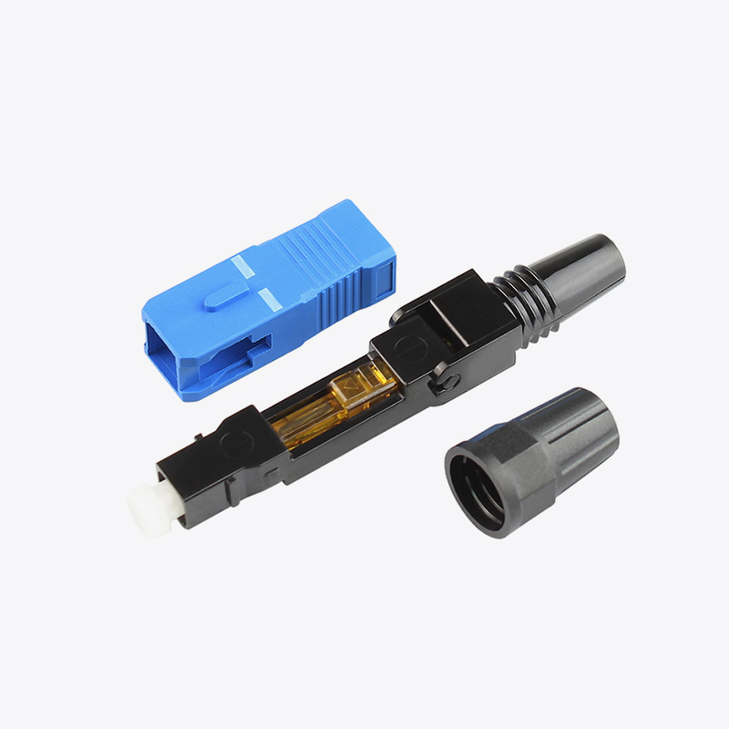
Field termination deserves special attention. Quick connectors and field-installable terminations make FTTH rollouts practical, but their insertion loss depends heavily on cleave angle, fiber protrusion, and insertion technique. When the cleave angle exceeds one degree or the fiber protrusion falls outside the specified range, both insertion loss and return loss deteriorate. TRTCABLE produces fast connector technology with controlled ferrule geometry so that installers can reach repeatable results — but only when they follow the recommended procedure step by step.
 T4-01 Quick Assembly Field ConnectorThis fast connector enables rapid field termination of drop and indoor cables, with high installation success and reliability. It is designed for FTTH rollouts where cleave angle and fiber protrusion must stay within specified ranges to keep insertion and return loss low.View Product →
Testing and Acceptance Thresholds
Before you accept a link, measure the insertion loss of the channel and, where possible, of every connector pair. An optical loss test set (OLTS) gives the end-to-end insertion loss of the whole channel, while an OTDR displays the loss of each individual event — every connector, splice, and bend along the fiber.
Use these thresholds as a practical starting point:
- Single connector pair: 0.5 dB maximum; treat 0.3 dB as the design target for single-mode.
- Total channel: calculate it from the link budget, including fiber attenuation, splices, connectors, and a safety margin.
- OTDR event: compare the measured event loss with the reference patch cord loss and the launch-cable conditions, because an OTDR measures relative to its reference point.
When a connector exceeds its threshold, do not replace it right away. Clean it, inspect it, and remeasure. A large percentage of "bad" connectors turn out to be dirty connectors. If loss persists after cleaning, check the adapter, then examine the end face geometry with an interferometer if one is available.
Frequently Asked Questions
Q1: What is a normal insertion loss for an SC/APC connector pair?
A properly mated SC/APC pair should measure no more than 0.3 dB, and good components often reach 0.15 dB or lower. If you consistently see more than 0.5 dB, inspect and clean the end faces and check the adapter alignment.
Q2: Does APC or UPC polish affect insertion loss?
Both polishes can achieve low insertion loss; the main difference is return loss. APC end faces are angled at 8 degrees to suppress reflectance, which is why APC is preferred for RFoG and high-density PON systems. As long as you do not mix the two types, either polish can meet a 0.3 dB insertion loss target.
Q3: Why does a connector pair show different insertion loss values in two directions?
Because the two connectors are not identical. The loss of a pair is the sum of mismatch loss, offset loss, and geometry differences; measure in both directions and use the higher value as the acceptance criterion, or use the average for a splice, depending on your standard.
Q4: Can high insertion loss damage a fiber link?
High insertion loss itself does not damage the fiber, but a contaminated end face under high optical power can absorb heat and burn, which causes permanent damage. That is one more reason to inspect before you mate high-power transceivers.
 Address:Zhong'an Road, Puzhuang Town, Suzhou City, Jiangsu Prov., China
 Phone:+86-189 1350 1815
 Tel:+86-512-66392923
 Fax:+86-512-66383830
 Email:[email protected]
 Wechat: xiaobin18913501815
 whatsapp: +86 18913501815

 0