
 English
 русский
 Español
 Português
 عربى
عربى


ADSS Fiber Cable Installation Considerations: Key Factors for Reliable Aerial Networks
An all-dielectric self-supporting (ADSS) fiber optic cable is one of the most efficient methods for carrying optical fibers across long aerial spans because it supports its own weight and requires no messenger wire or steel lashing. That efficiency, however, disappears quickly when installation planning ignores the cable’s real mechanical limits. In practice, most ADSS failures — strained fibers, high splice loss, or premature sheath cracking — trace back to decisions made before the cable leaves the drum: underestimated ice and wind loads, incorrect sag settings, incompatible hardware, or rushed pulling and splicing. This article focuses on the installation considerations that separate a reliable aerial network from a costly maintenance problem.
Start With an ADSS Cable Matched to the Route
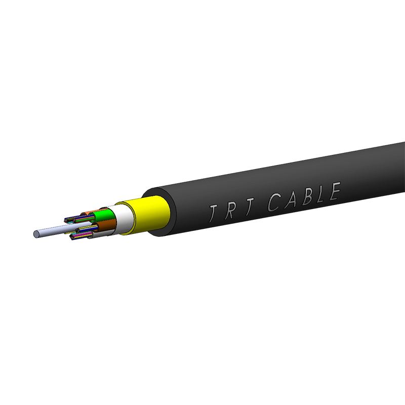
ADSS cable construction is simple in concept but demanding in detail. The cable has no metallic components; aramid strength yarns carry the mechanical load, and a UV-resistant outer sheath protects the fibers from years of sun and weather. Because there is no metal path, ADSS is well suited for routes near power lines and for long spans where a messenger wire would add cost and installation time.
The first installation consideration is therefore specification. You need a cable with the correct fiber count, sheath material, and rated span capability for the worst span on the route, not the average one. A structured approach to choosing the right fiber optic cable type helps prevent mismatches between the cable rating and the physical route.
All-Dielectric Self-Supporting Outdoor ADSS Fiber Optic CableThis ADSS cable with aramid yarn strength members supports spans over 200 meters and a 30-year design life, making it the reference for span, tension, and sag calculations in your installation plan.View Product →
TRTCABLE publishes span, tension, and sag data for its outdoor ADSS cable series, and that data sheet should become the reference for the whole installation plan. Once the maximum allowable span, maximum working tension, and sag values for the relevant loading district are known, every later decision — pole capacity, hardware rating, pulling tension, splice enclosure selection — must stay inside that documented envelope.
Complete a Route Survey Before You Order Hardware
A route survey is not a formality; it is the input data for your sag and tension calculations. Walk or drive the full aerial route and record the conditions that actually exist at each support point.
- Measure every span length and the attachment height on each pole or structure.
- Record pole type, condition, and available capacity; an undersized pole is a common source of long-term problems.
- Identify crossings of roads, railways, power lines, and waterways because each one has clearance requirements.
- Note the local temperature range and prevailing wind direction; these values appear directly in the sag calculation.
- Determine the applicable loading district from the local code or the project specification.
| Parameter | What to verify | Why it matters |
|---|---|---|
| Span length | Actual pole-to-pole distance, not a drawing estimate | Determines sag, tension, and hardware rating |
| Clearance | Height above ground, roads, and other utilities | Prevents contact and code violations |
| Temperature range | Minimum and maximum values at the site | Controls tension change from summer to winter |
| Loading district | Wind and ice loads specified for the area | Defines the worst-case mechanical load |
| Pole capacity | Pole class, material, and condition | Avoids overloading the support structure |
A common planning mistake is designing to the average span while the route includes one unusually long span. The sag and tension calculation must use the ruling span and the worst case that actually exists on the ground, not the arithmetic mean of the drawings.
Respect Sag, Tension, and Hardware Limits
Sag and tension are two sides of the same calculation. At installation, the cable is set to a specified sag at a reference temperature. When the temperature rises, the cable slackens; when it falls, or when wind and ice add load, tension climbs to its maximum. The cable’s maximum working tension must never be exceeded throughout the design life.
Hardware that fits the cable
ADSS cable is held by dielectric dead-end grips or suspension clamps designed for the cable’s exact diameter. Armor-rod assemblies distribute the clamping force and add bending stiffness near the attachment point. Torque values on clamps matter; overtightening damages the sheath, and undertightening allows the cable to move and abrade.
Never use steel lashing or metal hardware directly on an ADSS cable. The all-dielectric design is intended to remove metallic elements from the span, and mixing metal hardware reintroduces corrosion and voltage-related risks.
Rule of thumb: if sag is set without the supplier’s sag and tension table, the span is being installed by guesswork.
Pull Carefully: Tension, Bend Radius, and Clearance Rules
Most ADSS sheath damage happens during the pull, not during service. The pulling method must distribute the force across the whole cable cross-section so the aramid yarns carry the load and the sheath is not overstressed.
- Use a swivel grip or pulling stocking that engages the full cable circumference, with a tension gauge in line.
- Pull slowly and steadily, without jerks. Many ADSS designs list a maximum installation tension in the range of 1.5 to 3 kN, but the exact value belongs to the chosen cable data sheet.
- Set up rollers or pulleys at every support point so the cable never rubs against a sharp edge, bracket, or rough surface.
- Keep the bend radius above the minimum during the entire pull; a kink in an ADSS cable is a permanent defect.
- Use the figure-8 method for long routes or when pulling in both directions from a single drum location.
Clearance is a safety issue as much as an engineering one. Even though ADSS is dielectric, installation crews must maintain the required approach distance to energized power conductors and coordinate any work near live lines with the line owner. Final sag must also preserve the required ground and crossing clearances under the worst loading condition.
Splice and Seal for a Long Service Life
The cable installation does not end when the span is strung; the most sensitive moment is the splice point. A pole-mounted or mid-span closure is exposed to the same sun, rain, and temperature swings as the cable, so it must be sealed for decades, not for one season.
Choose a fiber splice closure with a fiber count and cable entry diameter that match the installed cable. Organize splice trays so that each fiber has enough slack, keep the bend radius inside the trays above the limit, and seal every entry port completely. An aerial closure also needs proper mounting so water cannot pool at the cable entry.
For a useful overview of what makes a closure reliable, review how fiber optic splice closure design affects long-term network performance.
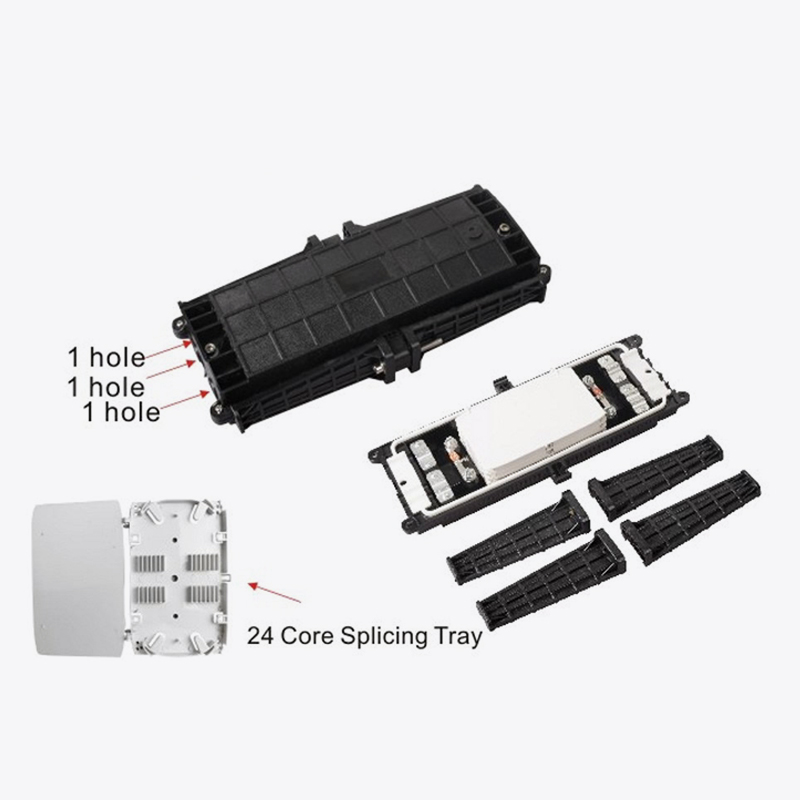 96-Core Fiber Optic Splice Closure for Sealed SplicingA PC-made 96-core closure with three inlet and outlet ports and waterproof rubber sealing, suitable for storing slack and protecting splices before and after OTDR testing.View Product →
Run an OTDR test after splicing and before closing the closure, then test again after the closure is sealed. Record the fiber attenuation values, the closure location, and the amount of slack stored. This documentation is what makes future repairs fast instead of painful.
Test, Document, and Avoid Common Pitfalls
After the last splice, finish with a full acceptance test. OTDR traces in both directions, insertion loss measurements per span, and a visual check of every attachment point will reveal problems while they are still cheap to fix.
Pitfalls that appear again and again
- Setting sag for summer temperatures and ignoring winter ice and contraction;
- Pulling without a tension gauge and exceeding the rated installation tension;
- Using metallic lashing or hardware on a dielectric cable;
- Ignoring pole strength or attaching to a damaged pole;
- Dragging the cable over sharp edges or onto the ground during the pull;
- Leaving closure entry ports unsealed so water enters the closure.
Document the as-built sag and tension values, closure identifiers, fiber mapping, and GPS coordinates for every splice point and pole. Aerial networks are easy to inspect but difficult to trace when records are missing.
Frequently Asked Questions About ADSS Installation
Q1: What is the maximum span for an ADSS fiber cable?
The maximum span depends on fiber count, sheath design, and the local loading district. Many ADSS cables are engineered for spans from 100 to 300 meters or more, but the only reliable number is the one stated for your specific cable and loading conditions.
Q2: Can ADSS cable be installed near high-voltage lines?
Yes. Because ADSS has no metallic components, there is no conductive path to induce currents, which is why it is a common choice for sharing infrastructure with power lines. Crews must still respect safe approach distances while handling the cable.
Q3: What is the minimum bend radius during ADSS installation?
A typical value used in planning is 20 times the cable outer diameter while pulling, and 10 times the cable outer diameter once installed. Confirm the exact minimum bend radius on the cable data sheet before starting the pull.
Q4: Why is sag so important in ADSS installation?
Sag controls the actual tension in the cable. Too little sag means tension rises under cold weather and ice loads, potentially exceeding the cable’s rated strength. Too much sag reduces clearance over roads and other utilities, creating a safety hazard. The sag value comes from the supplier’s sag and tension table, not from visual judgment.
An ADSS installation is only as reliable as the planning that precedes it. Match the cable to the route, complete a physical survey, set sag from the supplier’s table, pull within rated limits, protect the fiber during splicing, and document the as-built result. Follow those steps consistently, and the aerial network will deliver stable performance for decades.
 Address:Zhong'an Road, Puzhuang Town, Suzhou City, Jiangsu Prov., China
 Phone:+86-189 1350 1815
 Tel:+86-512-66392923
 Fax:+86-512-66383830
 Email:[email protected]
 Wechat: xiaobin18913501815
 whatsapp: +86 18913501815

 0
0