
 English
 русский
 Español
 Português
 عربى
عربى


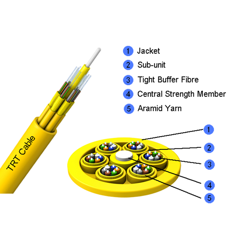
How to Choose the Right Fiber Optic Cable Types for Your Network Project
Why Fiber Optic Cable Selection Determines Network Performance
A poorly matched fiber optic cable is one of the most common causes of avoidable network downtime. Core geometry, jacket rating, and connector compatibility all interact with the physical environment where the cable is installed. Choosing the wrong outdoor cable for an indoor riser, or pairing multi-mode fiber with a single-mode transceiver, produces link failures that are expensive to diagnose after installation is complete.
This guide breaks down the practical differences between fiber types, explains how core diameter and color coding affect field work, and walks through the selection criteria that installers and network planners use before ordering material for a project.
9 / 125 um
Standard single-mode core and cladding size used for long-haul and backbone links
550 m
Typical maximum 10G link distance supported by OM4 laser-optimized multi-mode fiber
6 Types
Commonly deployed fiber categories across enterprise, carrier and data center networks
Single-Mode vs Multi-Mode: Core Differences That Matter
Every fiber optic cable types decision starts with choosing between single-mode and multi-mode glass. Single-mode fiber carries one light path through a narrow core, which minimizes signal spreading and supports distances beyond 10 kilometers. Multi-mode fiber uses a wider core that allows several light paths at once, which lowers component cost but limits transmission distance due to modal dispersion.
| Attribute | Single-Mode (OS2) | Multi-Mode (OM3/OM4) |
|---|---|---|
| Core Diameter | 9 microns | 50 microns |
| Light Source | Laser diode | VCSEL laser |
| Typical Max Distance | 10 km or more | 300 to 550 meters |
| Relative Transceiver Cost | Higher | Lower |
| Common Use Case | Carrier backbone, campus links | Data center, short building runs |
The radar comparison shows single-mode fiber leading on distance and bandwidth headroom, while multi-mode fiber scores higher on cost efficiency and installation simplicity because of lower-cost transceivers and wider alignment tolerance during termination.
Fiber Optic Cable Types Chart: Multi-Mode Distance Capability
Within multi-mode fiber, the generation designation (OM1 through OM5) reflects improvements in bandwidth-distance product achieved through tighter manufacturing tolerances and laser-optimized core profiles. The chart below compares maximum supported link distance at 10 Gbps for each generation.
OS2 single-mode fiber is not plotted on this chart because its practical distance, often 10 kilometers or beyond without amplification, sits far outside the multi-mode range and would compress the visual comparison between OM1 and OM5.
For campus backbones or metro connections, single-mode remains the default choice once distance exceeds 550 meters, since adding intermediate multi-mode segments introduces extra splice points and higher long-term maintenance cost.
Indoor vs Outdoor Fiber Selection: A Decision Workflow
Jacket material and strength members are selected based on where the cable physically runs, not just the optical specification. Outdoor cable needs moisture blocking and UV-resistant jacketing, while indoor cable must meet fire rating codes such as riser or plenum ratings for the space it passes through.
Many projects also use a transition point where an outdoor-rated distribution cable enters a building and terminates at a patch panel, after which indoor rated patch cords continue the link to equipment racks. This hybrid approach avoids running non-plenum jacket through air handling spaces while still using cost-effective outdoor cable for the majority of the outside run.
Fiber Optic Cable Color Codes and Buffer Identification
Color coding lets technicians identify individual fibers within a multi-fiber bundle without tracing the strand end to end. The industry standard sequence repeats every twelve fibers, which is why cables are commonly built in twelve-count sub-units.
| Position | Buffer Color | Position | Buffer Color |
|---|---|---|---|
| 1 | Blue | 7 | Red |
| 2 | Orange | 8 | Black |
| 3 | Green | 9 | Yellow |
| 4 | Brown | 10 | Violet |
| 5 | Slate | 11 | Rose |
| 6 | White | 12 | Aqua |
Jacket color also carries meaning at a glance. Yellow jacketing typically signals single-mode fiber, while orange or aqua jacketing signals multi-mode fiber, with aqua specifically reserved for laser-optimized OM3 and OM4 grades in many regional standards. Confirming jacket color against the printed cable legend before splicing prevents mixing fiber types on the same patch panel.
Fiber Network Bandwidth Capacity Growth Over Time
Bandwidth capacity supported over a single strand has grown consistently as laser modulation and multiplexing techniques improved. The line chart below tracks typical maximum per-wavelength capacity milestones across two decades of deployment.
This upward trend explains why network planners increasingly select single-mode fiber even in shorter runs, since the fiber itself rarely becomes the bottleneck once installed. Upgrading electronics later, rather than re-pulling cable, keeps the physical infrastructure useful across several equipment refresh cycles.
Installation Standards and Splicing Time Comparison
Fiber optic installation standards cover bend radius limits, pulling tension, and the termination method used at each end. Bend radius during installation is typically twenty times the cable outer diameter, and this drops to ten times the diameter once the cable is in a static, undisturbed position. Exceeding these limits raises attenuation and increases the risk of micro-cracking inside the glass core.
Pre-terminated assemblies cut installation labor dramatically because connectors are factory polished and tested before shipment, but they require accurate length measurement in advance since field trimming is not possible. Fusion splicing remains the standard for long backbone runs where continuous, low-loss joints outweigh the added labor time.
How to Choose the Right Fiber Network Cable for a Project
Selecting a fiber network cable comes down to matching four variables to the physical and operational requirements of the link: mode type, distance, environment, and fiber count.
- Confirm the required link distance and compare it against single-mode and multi-mode distance limits.
- Identify the installation environment, including exposure to moisture, sunlight, rodents, or fire code zones.
- Calculate fiber count with spare capacity, typically twenty to thirty percent above current need.
- Match connector type to existing equipment ports to avoid adapter panels adding extra loss.
- Verify pulling tension and bend radius limits against the planned conduit or tray path.
A cable specification that looks correct on paper can still fail in the field if the installation path includes tighter bends or longer pulls than the manufacturer rating allows. Route surveys before ordering material prevent costly change orders later.
Documenting the final selection, including fiber count, jacket rating, and connector style, in a labeling scheme also speeds up future moves, adds, and changes without requiring a full re-survey of the existing plant.
Frequently Asked Questions
Q1: What is the main difference between single-mode and multi-mode fiber?
Single-mode fiber uses a narrow core that carries one light path, supporting longer distances, while multi-mode fiber uses a wider core that supports multiple light paths over shorter distances at lower transceiver cost.
Q2: Can outdoor fiber cable be used inside a building?
Outdoor cable generally cannot be run inside occupied spaces because it lacks fire rating certification, though it can transition to a patch panel near the entry point where indoor rated cable continues the link.
Q3: How many fibers are typically bundled in a color-coded unit?
Standard color coding cycles every twelve fibers, so cables are commonly organized in twelve-count sub-units that repeat the same color sequence for higher fiber counts.
Q4: Why does OM4 fiber support longer distances than OM3?
OM4 fiber is manufactured with tighter core tolerances and a higher bandwidth-distance product, allowing it to support 10 Gbps links up to roughly 550 meters compared to about 300 meters for OM3.
Q5: What bend radius should be maintained during installation?
During active pulling, bend radius should stay at or above twenty times the cable outer diameter, relaxing to about ten times the diameter once the cable is installed and static.
Q6: Is single-mode fiber always the better choice?
Not necessarily. Multi-mode fiber remains cost effective for short data center runs where transceiver cost matters more than maximum reach, while single-mode is preferred once distance or future bandwidth headroom becomes the priority.
 Address:Zhong'an Road, Puzhuang Town, Suzhou City, Jiangsu Prov., China
 Phone:+86-189 1350 1815
 Tel:+86-512-66392923
 Fax:+86-512-66383830
 Email:[email protected]
 Wechat: xiaobin18913501815
 whatsapp: +86 18913501815

 0
0