
 English
 русский
 Español
 Português
 عربى
عربى


What Are the Critical Differences Between Indoor and Outdoor Fiber Optic Cable Deployment?
Deploying fiber optic infrastructure demands a clear understanding of environmental forces, mechanical stresses, and regulatory requirements that distinguish indoor from outdoor applications. While both share the same fundamental transmission principles, the Indoor Fiber Optic Cable and Outdoor Fiber Optic Cable ecosystems operate under vastly different constraints—from fire safety mandates to UV degradation and rodent resistance.
The 2025 Fiber Broadband Association report confirms that AI-focused data centers now require 36 times more optical fiber than traditional CPU-based racks, driving unprecedented demand for both indoor and outdoor cable infrastructure. This surge has made deployment best practices more critical than ever. Getting it wrong means premature cable failure, signal degradation, or even safety violations that can halt network operations.
Comparative Performance Metrics by Cable Type
Figure 1: Performance comparison across key mechanical and environmental parameters
Understanding the Core Cable Categories
Indoor Fiber Optic Cable and Outdoor Fiber Optic Cable serve fundamentally different purposes. The former prioritizes fire safety, flexibility, and ease of termination, while the latter emphasizes moisture protection, UV stability, and mechanical robustness.
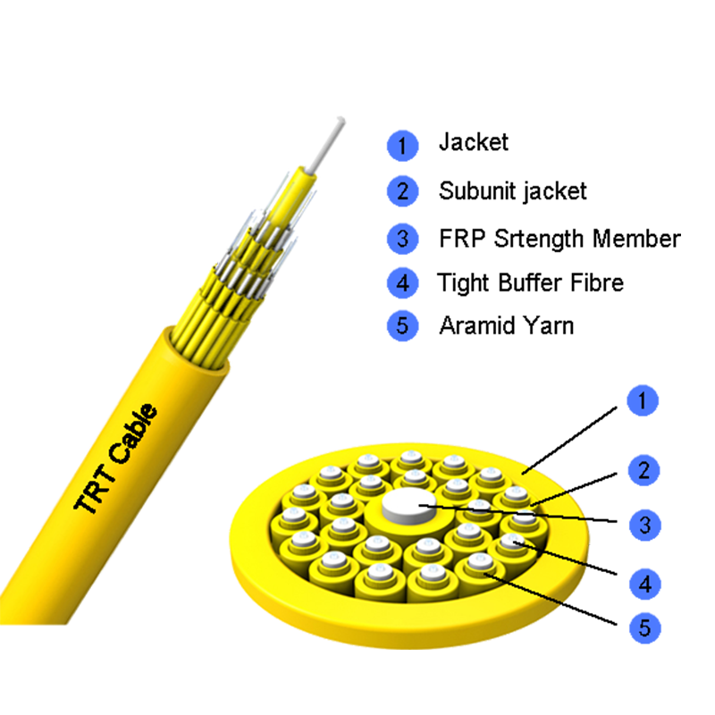
Figure 2: Indoor Fiber Optic Cable with tight-buffered construction
Indoor Fiber Optic Cable Characteristics
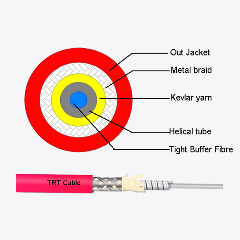
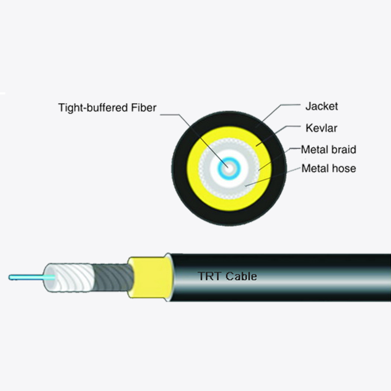
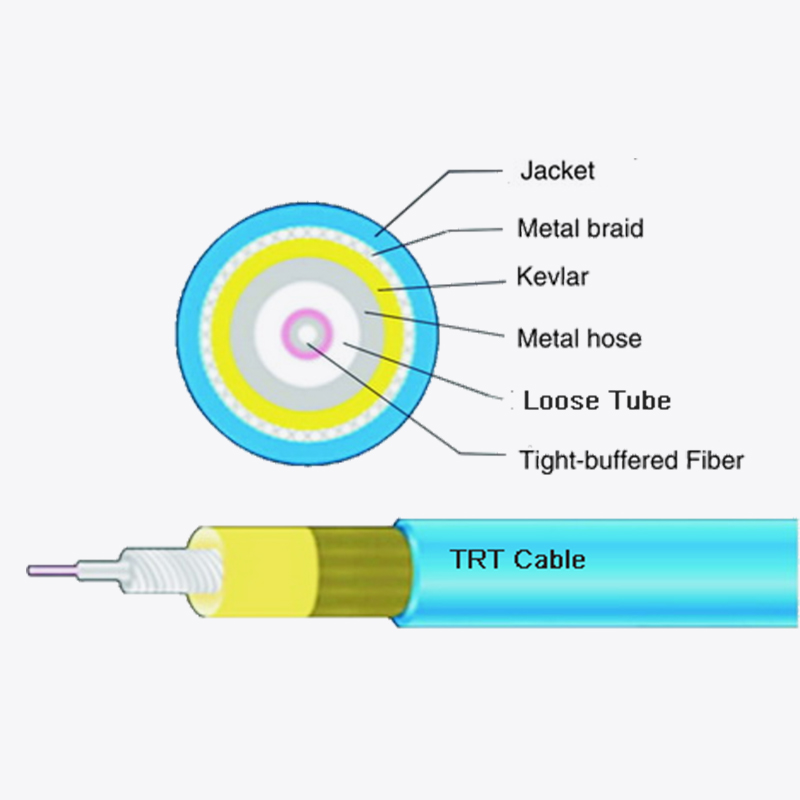
Indoor cables typically employ tight-buffered designs where a 900-micron buffer coating is applied directly over each fiber. This construction provides excellent crush resistance, simplifies connectorization, and eliminates the need for gel cleaning during termination. Fire rating compliance is non-negotiable—plenum-rated (OFNP) cables for air-handling spaces and riser-rated (OFNR) for vertical shafts are mandatory under most building codes.
Outdoor Fiber Optic Cable Characteristics
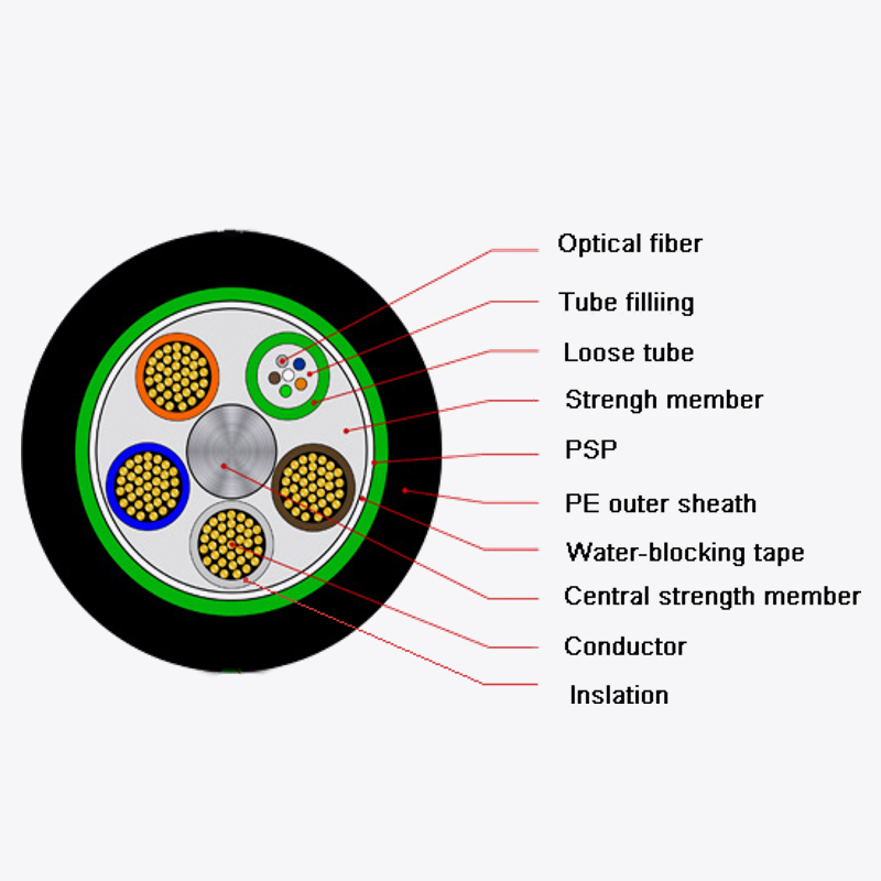
Outdoor cables predominantly use loose-tube designs with gel-filled or dry water-blocking elements that protect fibers from moisture ingress. These cables incorporate high-tensile strength members—typically aramid yarn—and feature jackets made from polyethylene (PE) or thermoplastic polyurethane (TPU) for superior UV and weather resistance. The Armored Cable variant adds an interlocking steel or corrugated tape layer for protection against rodents and mechanical impact.
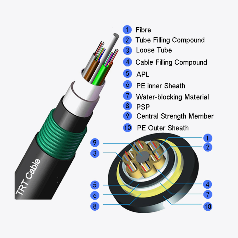
Figure 3: Outdoor Fiber Optic Cable with stranded loose-tube armored design
Fire Rating Standards for Indoor Fiber Cable
Fire safety is the single most important differentiator for indoor cable selection. The National Electrical Code (NEC) establishes clear classifications:
- OFNP (Plenum-rated): Suitable for air-handling spaces such as drop ceilings and raised floors. These cables use fluoropolymer jackets that emit minimal smoke and no toxic halogens when burned.
- OFNR (Riser-rated): Designed for vertical shafts between floors. While less stringent than plenum, OFNR cables must prevent flame propagation upward through a building.
- LSZH (Low Smoke Zero Halogen): Mandatory in many European and Asian jurisdictions for public spaces. These jackets produce limited smoke and corrosive gases, protecting human life and sensitive equipment during fires.
Industry data shows that proper fire-rated cable selection reduces life safety risks by over 60% in building fires. Transitioning from outdoor to indoor environments requires careful handling: outdoor cables entering a building must be terminated at the point of entry or transitioned to fire-rated indoor cables within 15 meters per most codes.
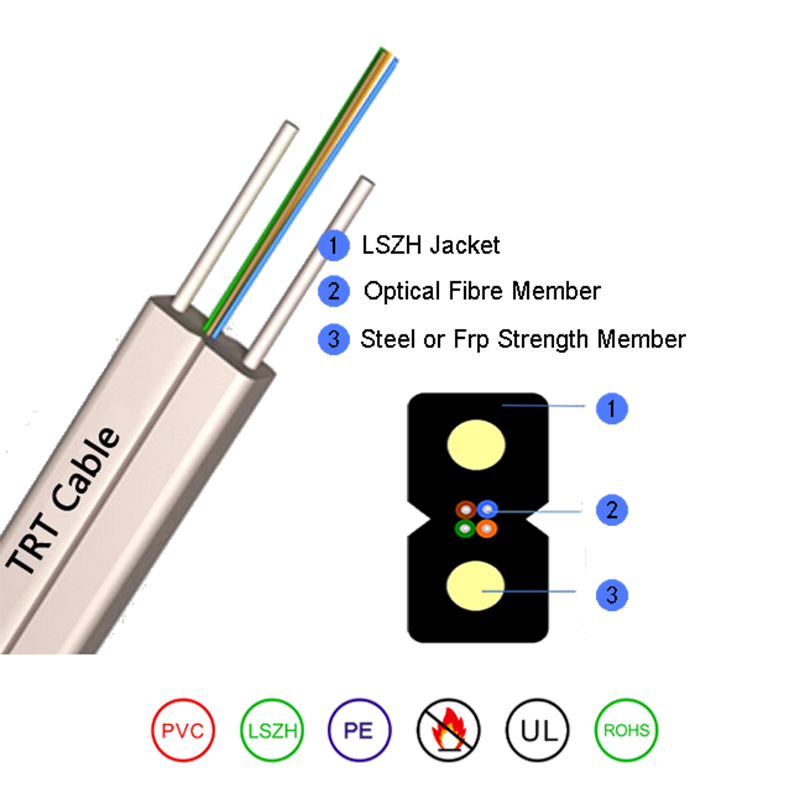
Figure 4: Drop Cable with bow-type construction for FTTx applications
Fiber Optic Cable Outdoor Jacket Materials and UV Resistance
The jacket is the first line of defense in outdoor deployments. Polyethylene (PE) remains the industry standard for its exceptional UV stability, moisture resistance, and dielectric properties—PE-jacketed cables can last 25+ years in direct sunlight without significant degradation.
For extreme conditions, TPU (Thermoplastic Polyurethane) offers superior abrasion resistance and flexibility at low temperatures, making it ideal for direct burial and industrial applications. The UV resistance mechanism involves carbon black additives that absorb harmful radiation; a 2–3% concentration provides lifetime protection against photodegradation.
Key selection guideline: For aerial installations above 5 meters, PE jackets with UV stabilizers are mandatory. For buried applications where UV isn't a concern, focus instead on crush resistance and moisture barriers.
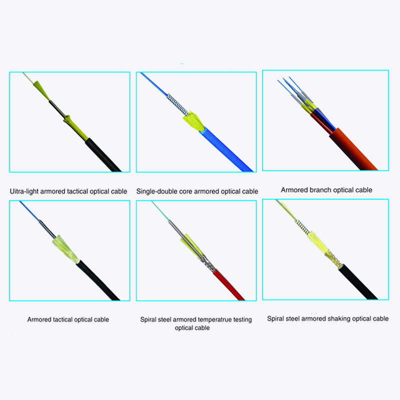
Figure 5: Armored Cable with flexible interlocking steel armor layer
Armored Cable Protection Against Rodents and Mechanical Threats
Rodent damage accounts for an estimated 15–20% of all outdoor fiber cable failures in suburban and rural deployments. Armored Cable solves this through two primary designs:
- Corrugated steel tape armor: Wrapped helically around the cable core, this design offers excellent protection against gnawing rodents and heavy excavation equipment. Typical steel tape thickness ranges from 0.15–0.25 mm.
- Interlocking aluminum or steel armor: Used in flexible armored cables, this design provides similar protection while maintaining bendability—critical for installations requiring tight radius turns.
Research indicates that armored cables reduce rodent-related failure rates by 85% compared to unarmored alternatives. The cost premium of 20–40% is justified by a projected 5–7 year extension in service life for buried installations.
Cumulative Failure Rate by Protection Level (5-Year Period)
Figure 6: Cumulative failure rates for armored versus unarmored outdoor cables
Aerial vs Buried Fiber Drop Cable: Method Comparison
The Drop Cable represents the final connection leg from distribution networks to subscriber premises. Deployment method selection significantly impacts long-term reliability.
| Parameter | Aerial Drop Cable | Buried Drop Cable |
|---|---|---|
| Installation Speed | Rapid (hours) | Slow (days) |
| Cost per Meter | Low | High (trenching) |
| Vulnerability | Wind, ice, UV | Rodents, excavation |
| Recommended Depth | N/A (5m+ pole height) | 1.2–1.5 meters |
| Typical Jacket | PE with UV stabilizer | TPU or armored PE |
For aerial deployments, self-supporting cables with integrated messenger wires (such as ADSS designs) are preferred. These cables withstand wind loads up to 200 km/h and ice accretion of 25 mm when properly tensioned. Buried installations demand trenching to frost-line depth (typically 1.2–1.5 meters) with sand bedding and warning tape placement every 50–100 meters.
Environmental Suitability Radar: Cable Type Performance
Indoor and Outdoor Fiber Optic Cable Installation Guidelines
Successful deployment hinges on adherence to mechanical limits. The Fiber Optic Association (FOA) specifies two critical parameters:
- Maximum pulling tension: Under no circumstances should installation tension exceed 200–400 N for outdoor cables, depending on design. Indoor tight-buffered cables typically have lower limits (100–150 N) due to their smaller strength members. Exceeding these limits causes micro-bending and permanent signal loss.
- Minimum bend radius: During pulling, maintain a radius of at least 20 times the cable diameter. After installation, 10 times the diameter is acceptable. For a 13 mm cable, this translates to 260 mm under tension—a pulley diameter of 520 mm.
Pulling Best Practices
- Use swivel pulling eyes to prevent cable twisting during installation.
- Apply cable lubricants compatible with the jacket material—polyethylene-based lubricants for PE jackets, water-based gels for TPU.
- For long conduit runs exceeding 100 meters, install pull boxes every 30–50 meters to reduce tension.
- Consider automated pullers with tension monitoring—these devices can reduce damage incidents by 70% compared to manual methods.
Root Causes of Fiber Optic Cable Failure
Figure 8: Primary failure causes in fiber optic cable networks (industry survey data)
Indoor Installation Safety and Cable Management
Indoor environments present unique challenges including limited space, fire safety requirements, and cable congestion.
Cable Management Best Practices
- Use J-hooks, ladder racks, and cable trays to support cables above ceiling tiles or under raised floors. Support intervals should not exceed 1.5 meters.
- Maintain 30 mm minimum separation between fiber optic and power cables to avoid electromagnetic interference.
- Bundle cables of the same type together with cable ties spaced 200–300 mm apart. Leave approximately 100 mm slack at turns to facilitate maintenance.
- Attach clear labels at both ends, joints, and turns of each cable—labeling reduces troubleshooting time by up to 50% in congested data centers.
Outdoor to Indoor Transition Points
One of the most critical—and frequently mishandled—aspects of deployment is the transition between outdoor and indoor environments. The entry point must achieve three objectives simultaneously: physical protection, water sealing, and fire rating compliance.
- Transition enclosures: Use dedicated splice closures or termination boxes at building entry points. These enclosures must be IP-rated for water resistance and provide strain relief for both cable types.
- Waterproofing: Seal conduit entries with silicone gel or waterproof tape. A drip loop before entry prevents water from following the cable into the building.
- Fire stopping: Use fire-rated putty or intumescent seals around cables passing through fire-rated walls.
Industry data suggests that proper transition practices extend cable service life by 3–5 years compared to installations where entry points are inadequately protected.
Fiber Optic Cable Selection Decision Flowchart
Outdoor Construction Methods: Conduit, Direct Burial, and Aerial
Conduit Installation
High-density polyethylene (HDPE) conduit is the standard for underground runs. Install with a 1–2% slope for drainage, smooth all transition points to avoid sharp edges, and limit runs to 100 meters between pull boxes. Conduit size should be at least 1.5 times the cable diameter; for armored cables, 2 times is recommended.
Direct Burial
Armored cables with TPU or double-jacketed PE are mandatory for direct burial. Trench depth should be 1.2–1.5 meters below the frost line—shallower depths risk temperature-related damage. Line the trench bottom with 10–15 cm of sand, lay the cable without twists, and cover with another sand layer before backfilling. Warning tape should be placed 30–50 cm above the cable to prevent future excavation damage.
Aerial Installation
ADSS (All-Dielectric Self-Supporting) cables are preferred for long-span aerial routes due to their integrated strength members. For shorter spans, lashed cables on messenger wires remain cost-effective. Anticipate environmental loading: wind, ice, and temperature fluctuations must be factored into sag and tension calculations.
Pre-Terminated Solutions and Deployment Efficiency
Pre-terminated fiber assemblies have demonstrated significant deployment advantages. Corning reports that over 100 million factory-terminated connectors have been deployed globally with exceptionally low failure rates. These solutions eliminate field splicing, reducing installation time by up to 70% and cutting labor costs substantially.
Modern pre-terminated connectors achieve insertion losses as low as 0.25 dB—comparable to fusion splices—with the added benefit of predictable, repeatable performance. For high-density data centers, MPO trunk cables with 12, 24, or 144 fibers per connector provide space savings exceeding 50% compared to traditional single-fiber terminations.
Frequently Asked Questions
Q1: What is the primary difference between indoor and outdoor fiber optic cables?
Indoor fiber optic cables prioritize fire safety and flexibility, featuring tight-buffered designs and fire-rated jackets (OFNP, OFNR, or LSZH). Outdoor fiber optic cables emphasize environmental protection—UV resistance, moisture barriers, and mechanical strength—using loose-tube designs with PE or TPU jackets.
Q2: When should I use armored cable instead of standard outdoor cable?
Armored cable is recommended for direct burial installations, rodent-prone areas, and locations with heavy mechanical traffic. It provides 85% greater protection against physical damage and extends service life by 5–7 years compared to unarmored alternatives. The 20–40% cost premium is justified by reduced maintenance and failure rates.
Q3: Can outdoor fiber optic cable be used indoors?
Outdoor cables can be brought indoors but must be terminated at the point of entry or transitioned to fire-rated indoor cables within 15 meters per most building codes. Outdoor cables typically lack the fire-rated jackets required for indoor use and may violate safety regulations.
Q4: What is the minimum bend radius for fiber optic cable during installation?
During pulling (under tension), the minimum bend radius is 20 times the cable diameter. After installation (no tension), the minimum is 10 times the diameter. For a typical 13 mm cable, this means 260 mm during pulling and 130 mm after installation.
Q5: How does UV exposure affect outdoor fiber optic cables?
UV radiation degrades cable jackets over time, causing cracking, embrittlement, and moisture ingress. High-quality PE jackets with 2–3% carbon black additives provide 25+ years of UV resistance. TPU jackets offer similar protection with enhanced flexibility at low temperatures. Without UV stabilizers, jacket failure can occur within 2–5 years.
Q6: What are the fire rating requirements for indoor fiber optic cables?
OFNP (plenum-rated) is required for air-handling spaces such as drop ceilings and raised floors. OFNR (riser-rated) is suitable for vertical shafts between floors. LSZH (Low Smoke Zero Halogen) is mandatory in many jurisdictions for public spaces, producing limited smoke and corrosive gases during fires.
Q7: What is the recommended burial depth for direct buried fiber cables?
Direct buried cables should be installed at 1.2–1.5 meters deep, below the frost line to prevent freeze-thaw damage. A 10–15 cm sand bedding layer beneath and above the cable protects against sharp debris. Warning tape should be placed 30–50 cm above the cable to prevent excavation damage.
Q8: What pulling tension should be applied to fiber optic cables?
Maximum pulling tension varies by cable type: armored outdoor cables typically support 400 N, loose-tube outdoor cables support 300 N, and indoor tight-buffered cables support 150–200 N. Exceeding these limits causes micro-bending and permanent signal loss.
 Address:Zhong'an Road, Puzhuang Town, Suzhou City, Jiangsu Prov., China
 Phone:+86-189 1350 1815
 Tel:+86-512-66392923
 Fax:+86-512-66383830
 Email:[email protected]
 Wechat: xiaobin18913501815
 whatsapp: +86 18913501815

 0
0