
 English
 русский
 Español
 Português
 عربى
عربى


How to Select and Manage Fiber Optic Patching Hardware for High-Density Networks
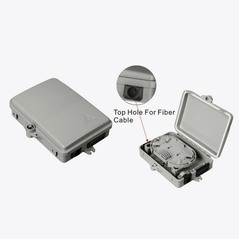
Fiber optic patching and connectivity hardware forms the physical foundation of modern telecommunications, data centers, and enterprise networks. The ecosystem of Patch Cord assemblies, Fiber Optic Cabinet infrastructure, and Fiber Optic Box-FTTH termination points must work in concert to deliver reliable, high-bandwidth services. This guide examines the technical specifications, capacity planning strategies, and maintenance protocols that define robust fiber connectivity hardware, providing actionable insights for network architects and field engineers.
Fiber Optic Patch Cord Types and Connector Interfaces
Understanding the LC, SC, ST, and FC Ecosystem
Fiber optic patch cords are distinguished by their connector interface, ferrule size, and polishing profile. The four primary connector types—LC, SC, ST, and FC—each offer distinct mechanical and optical characteristics suited to specific deployment scenarios [citation:2][citation:8].
- Lucent Connector (small form-factor)
- 1.25 mm ferrule, half the footprint of SC
- Push-pull latching mechanism
- Dominant in single-mode high-density applications
- Common on SFP transceivers
- Subscriber Connector / Square Connector
- 2.5 mm ferrule, push-pull coupling
- Most widely deployed in telecom and data networks
- Cost-effective, rated for 1,000 mating cycles
- Typical insertion loss < 0.25 dB
- Straight Tip (bayonet twist-lock)
- 2.5 mm ferrule, spring-loaded
- Widely used in multimode LAN environments
- Rated for 500 mating cycles
- Common in legacy building and campus networks
- Fixed Connector (threaded barrel)
- 2.5 mm ferrule, metal housing
- Preferred in high-vibration environments
- Common in test equipment and lasers
- Gradually being replaced by SC and LC
Connector Type Comparison Data
Polishing Profiles: PC, UPC, and APC
Beyond connector geometry, the end-face polishing profile determines return loss performance and reflectance characteristics [citation:14]. Physical Contact (PC) connectors use a slightly curved spherical end face to eliminate the air gap between mating fibers. Ultra Physical Contact (UPC) extends polishing to achieve superior surface finish, commonly applied in digital and telephony applications. Angled Physical Contact (APC) features an 8-degree angled end face that minimizes back-reflection, making it the preferred choice for CATV and analog transmission systems where signal clarity is paramount.
Fiber Optic Cabinet and FTTH Box Infrastructure
Fiber Optic Cabinet Capacity Planning
Fiber optic cabinets serve as centralized distribution points in outside plant (OSP) environments, housing splitters, splices, and termination panels. Modern cabinets scale from low-density 12-port configurations to high-capacity 1,152-port systems, enabling network operators to align capital investment with subscriber growth [citation:11].
Cabinet Capacity Scaling
Fiber Optic Box-FTTH: Last-Mile Termination
FTTH boxes provide the final termination point for fiber-to-the-home deployments, typically mounted on exterior walls or in building basements. These enclosures offer ingress protection for optical splitters, splices, and drop cable terminations, securing the transition from distribution networks to subscriber premises. Proper sealing and strain relief are essential to maintain signal integrity across the environmental exposure inherent in last-mile installations.
Rack-Mount Fiber Enclosure Guide
Modular Chassis and Backplane Architecture
Rack-mount enclosures provide centralized mounting for fiber terminations, patch panels, and splice trays within equipment racks [citation:4][citation:10]. A modular chassis design leverages a backplane system that distributes power and maintains consistent electrical connectivity across installed modules, eliminating external power adapters and reducing cable clutter. Standard rack heights range from 1RU to 4RU, with capacity scaling based on fiber count and connector density [citation:13].
| Enclosure Size | Typical Fiber Capacity | Adapter Type | Application |
|---|---|---|---|
| 1RU | 12–24 fibers | LC duplex / SC | Compact enterprise |
| 2RU | 48–72 fibers | LC / SC / MPO | Data center aggregation |
| 4RU | 144+ fibers | LC / MPO | High-density core |
Installation Best Practices for Rack Enclosures
- Plan load distribution by mounting heavier chassis equipment toward the lower portion of the rack to improve stability and reduce tipping risk [citation:4].
- Maintain proper grounding to protect sensitive electronics from static discharge and electrical interference.
- Reserve vertical space for cable managers and leave extra room for future expansion—structured cabling should provide approximately 30% initial overcapacity [citation:3].
- Secure each module evenly to prevent partial seating that can result in intermittent network behavior.
Rack Enclosure Installation Workflow
Best Practices for Fiber Optic Cable Management
Bend Radius Protection and Strain Relief
Fiber optic cables require precise handling to maintain signal integrity. Maintaining the specified bend radius—the minimum curvature a cable can tolerate without inducing micro-bending losses—is critical in both rack environments and outside plant installations [citation:15]. Cable management components such as low-profile fiber reels, modular routing guides, and 90/180-degree corner components help maintain defined bend radii while storing excess fiber slack in controlled, accessible configurations.
Strain relief components, including panel-mount glands with integrated gaskets and protective fiber boots, shield terminations from mechanical stress and environmental exposure [citation:15]. These components are essential in high-vibration environments, industrial control panels, and telecom enclosures where cables are subject to movement or tight routing constraints.
Bend Radius Requirements by Cable Type
Color-Coding and Labeling Standards
Adherence to structured labeling and color-coding standards—such as TIA-606-C—significantly reduces troubleshooting time and prevents misidentification during maintenance [citation:9]. Common schemes include yellow jackets for single-mode fiber, orange for multimode, and blue for single-mode with APC polish. Heat-shrink tubing labels offer superior durability compared to adhesive labels, remaining legible in high-temperature or high-abrasion environments.
- Implement standardized color codes for cable jacket identification
- Use QR codes or barcoded labels for asset tracking and inventory management
- Document all patch panel assignments with slot maps and cable records
- Maintain consistent labeling at both cable ends for efficient servicing
Patch Cord Testing and Maintenance
Insertion Loss and Return Loss Measurement
Regular testing of patch cords is essential to verify network performance and identify degradation before it impacts service. Insertion loss—the reduction in optical power from input to output—is the primary metric, typically measured using an optical loss test set (OLTS) or power meter and light source combination [citation:6]. Industry standards specify maximum insertion loss values of 0.3 dB for single-mode and 0.5 dB for multimode patch cords [citation:6].
Maintenance Protocols and Troubleshooting
- Inspect connector end-faces using video inspection probes to detect contamination or damage before testing [citation:6].
- Use optical time-domain reflectometers (OTDRs) for detailed fault localization, identifying breaks, splices, and connector events.
- Maintain detailed documentation of test results and service records for trend analysis and predictive maintenance.
- Implement automated validation systems that test connections immediately after patching to reduce human error.
Frequently Asked Questions
Q1: What is the difference between single-mode and multimode patch cords?
Single-mode patch cords use a 9 µm core and support one propagation mode, making them suitable for long-distance transmission (up to 100 km or more). Multimode patch cords use a 50 or 62.5 µm core and support multiple modes, optimized for shorter distances within data centers and campus networks. The core size difference determines the cable's bandwidth-distance product and application suitability.
Q2: How do I choose between LC, SC, and ST connectors?
LC connectors are preferred for high-density applications due to their small form factor (half the footprint of SC). SC connectors are the most widely used general-purpose connector, offering reliability and cost-effectiveness. ST connectors are commonly found in legacy multimode networks and educational environments. Selection should be based on existing infrastructure, space constraints, and transceiver compatibility.
Q3: What is the typical insertion loss specification for a patch cord?
Industry standards specify maximum insertion loss of 0.3 dB for single-mode patch cords and 0.5 dB for multimode patch cords when tested under reference conditions [citation:6]. Premium-grade patch cords often achieve 0.2 dB or lower. Return loss varies by polish type, with APC connectors providing the lowest reflectance (typically 60 dB or better).
Q4: How often should patch cords be tested?
Patch cords should be tested during initial installation, after any physical reconfiguration, and as part of routine preventive maintenance schedules—typically every 12 to 24 months in enterprise environments. High-use patching areas (data centers with frequent moves, adds, and changes) may require more frequent testing, especially if connectors show signs of wear or contamination.
Q5: What capacity should I plan for in a fiber optic cabinet?
Capacity planning should account for current termination requirements plus future growth—industry practice suggests provisioning 30% overcapacity initially, with modular expansion capability [citation:3]. Cabinet classes range from 12-port entry-level systems to 1,152-port high-density configurations. The choice depends on subscriber density, service area, and network growth projections.
 Address:Zhong'an Road, Puzhuang Town, Suzhou City, Jiangsu Prov., China
 Phone:+86-189 1350 1815
 Tel:+86-512-66392923
 Fax:+86-512-66383830
 Email:[email protected]
 Wechat: xiaobin18913501815
 whatsapp: +86 18913501815

 0
0