
 English
 русский
 Español
 Português
 عربى


Fusion Splicing Fiber Optic Cables: Process, Equipment, and Best Practices
Every FTTH installation, data center build, and long-haul route has one connection point that can quietly decide whether the network meets its design target: the fiber splice. Fusion splicing is the process of welding two bare optical fibers together with an electric arc. It remains the preferred method for permanent links because the splice creates a continuous, low-loss, and stable connection that can easily outlive the surrounding cable. If you are a network planner, field technician, or procurement engineer, the decisions you make around cable selection, splice protection, and work practices directly shape the quality and lifespan of every splice you produce.
What Is Fusion Splicing?
Fusion splicing joins two optical fibers by aligning their cores and melting the endfaces in an electrical arc. The molten glass fuses into a single continuous element, so light travels through the joint without a physical interface. That is why fusion splicing is treated as the gold standard for permanent fiber connections.
In contrast, mechanical splicing clamps two fibers together inside a small connector or sleeve with index-matching gel. Mechanical splices are useful for quick temporary restorations and emergency repairs, but they introduce an air gap or gel layer that causes light scattering. Typical insertion loss for a mechanical splice is 0.2 to 0.5 dB, while a good fusion splice on single-mode fiber is 0.02 to 0.05 dB. This is a 10x performance gap that matters for long spans and high-bandwidth links.
How the Fusion Splicing Process Works
Every fusion splice follows the same five-step sequence. The steps look simple, but rushing any one of them is the leading cause of rework on real projects.
- Strip the cable. Remove the outer jacket, strength members, buffer tubes, and coating layers to expose bare fiber. The strip length should match the splice protector or closure requirements.
- Clean the bare fiber. Wipe the stripped fiber with lint-free tissue soaked in alcohol to remove dust, coating residue, and static charge.
- Cleave the endface. Use a precision fiber cleaver to create a mirror-smooth end face perpendicular to the fiber axis. Acceptable cleave angle is typically less than 0.5 degree.
- Fuse the prepared ends. Place both fibers in the splicer, align the cores, and apply a controlled electrical arc. The splicer advances the fibers and fuses them into a single continuous glass path.
- Protect the splice. Position a heat-shrink sleeve over the splice and heat it to collapse and seal.
Before you close the splice tray, it is important to think about the enclosure that will protect the splices for years. A compact 96-core fiber optic splice closure offers sealed protection for outdoor FTTH distribution and allows for future expansion.
96-Core Outdoor Fiber Optic Splice Closure for FTTH DistributionThis compact splice closure provides sealed protection for up to 96 splices, suitable for outdoor FTTH distribution. With multiple ports and waterproof sealing, it helps maintain long-term splice performance and simplifies future expansion.View Product →Why Fusion Splicing Matters for Network Performance
Splice loss is not just a lab number. It translates directly into link reach, power budgets, and long-term error rates. OTDR traces done at commissioning can reveal a spike at a splice point even when an end-to-end power meter test looks healthy. That invisible spike becomes a maintenance issue after a few years of temperature swings and cable movement.
Typical splice loss benchmarks: single-mode fusion splice 0.02-0.05 dB; multimode fusion splice 0.05-0.10 dB; mechanical splice 0.2-0.5 dB; damaged or dirty splice above 1 dB (rework required).
For network operators, using fusion splicing keeps the attenuation budget safe for long-distance transmission and future upgrades. Lower per-splice loss also helps maintain an acceptable data rate for protocols that have strict receive sensitivity limits.
Choosing the Right Fiber Optic Cable for Fusion Splicing
Fusion splicing performance depends on the quality of the bare fiber and the design of the cable around it. For aerial, duct, or buried outdoor routes, you need a cable that protects the fibers during construction and keeps them stable when the closure is opened and closed. A guide to cable types can help you match the structure to the environment. One strong option is a stranded loose tube armored cable, which gives excellent mechanical protection for fused splices in harsh conditions.
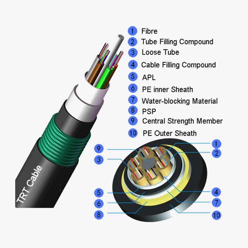 Stranded Loose Tube Armored Cable for Harsh EnvironmentsThis GYTA53 armored cable offers robust mechanical protection and water resistance, ideal for outdoor routes. Its stranded loose tube design ensures stable fiber placement and reliable fusion splicing in demanding conditions.View Product →
For FTTH drop segments, self-supporting bow-type drop cables are much faster to strip and splice because they offer simple, flat access to strength members and a consistent coating. Tight-buffer indoor cables also splice directly without needing tube removal. Pay attention to jacket materials too: LSZH (Low Smoke Zero Halogen) jackets are recommended for indoor areas but may be more abrasive on cleaver blades.
The real principle is to choose a cable whose stripped fiber geometry exactly matches the splicer's programs. Different fiber types, coating diameters, and buffer materials can affect arc power and fusion time. Request a splicing test from the cable manufacturer before a large rollout.
Common Fusion Splicing Problems and How to Fix Them
Even with a good splicer and clean hands, field conditions can force one of these classic problems:
- High splice loss. Causes include poor cleave angle, dirty endfaces, or incorrect arc parameters. Reclean, re-cleave, and check the splicer's arc calibration.
- Fiber breaks after splicing. Usually a short strip length, an oversized shrink tube, or a loose splicer V-groove. Follow the manufacturer's strip length table and use the correct splice protector.
- Air gap or rounded splice. The arc energy was too high, or the fiber feed was too far. Adjust the splice program for the specific fiber and re-splice.
- Fiber twisting inside the closure. The loose tube fibers may spring back after the closure is sealed. Secure the fibers in the splice tray and use strain-relief management.
- Measurement drift in cold weather. Humidity and wind affect arc discharge and cleaving. Work under a wind shield, and always store the cleaver and splicer in a stable temperature environment.
Fusion Splicing Best Practices for Field Technicians
Before powering on the splicer, set the work area to a controlled state. Use a clean, flat table; keep the cleaver blade clean with alcohol every 50 cleaves; and close the splicer's wind cover during every arc. Store the splice tray in a sealed bag until the closure is closed, and record the predicted loss and OTDR trace for every splice.
Practice discipline:
- Always inspect the fiber endface with the splicer's built-in magnification function.
- Never touch the bare fiber after cleaning.
- Make sure the splice protector is centered over the splice before heating.
- Use a fiber stub or fan-out pigtail when you need to connect to optical transceivers.
These habits are inexpensive, but they prevent the most expensive fault in fiber networking: an invisible splice defect that fails years later.
Frequently Asked Questions About Fusion Splicing
Q1: What is the difference between fusion splicing and mechanical splicing?
Fusion splicing welds two fibers together with an electric arc and achieves very low loss, typically 0.02 to 0.05 dB on single-mode fiber. Mechanical splicing aligns the fibers in a clamp with index-matching gel and has higher loss, around 0.2 to 0.5 dB.
Q2: How many fibers can be spliced in one closure?
Standard splice closures range from 12 to 288 cores. Higher fiber counts require larger trays and careful ribbon-only or loose-tube routing that still allows re-entry.
Q3: Do I need an OTDR to verify splice quality?
Yes. An OTDR trace is the only reliable field evidence to see if a splice is low loss and free from reflection. A power meter test can hide a bad splice in a short link, but the OTDR shows the spike clearly.
Fusion splicing is a discipline that pays for itself in long-term network stability. By selecting the right cable and splice closure, keeping the work area clean, and verifying every splice with OTDR testing, you create a low-loss path that can carry data reliably for decades. Whether you are expanding an FTTH network or building a data center backbone, the splice point will be one of the most important physical elements of your project.
 Address:Zhong'an Road, Puzhuang Town, Suzhou City, Jiangsu Prov., China
 Phone:+86-189 1350 1815
 Tel:+86-512-66392923
 Fax:+86-512-66383830
 Email:[email protected]
 Wechat: xiaobin18913501815
 whatsapp: +86 18913501815

 0