Web Menu
Product Search
Exit Menu
What is an Optical Fiber Termination Box?
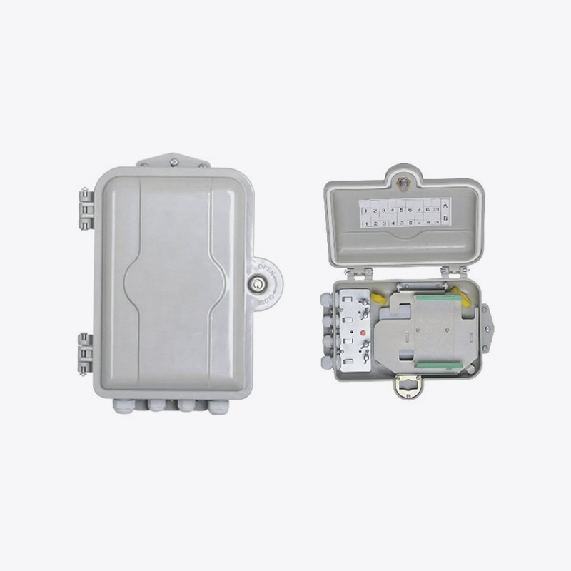
What is an Optical Fiber Termination Box?
In the vast and intricate network of modern telecommunications, the journey of a beam of light carrying immense amounts of data is both remarkable and complex. This light travels through the core of an optical fiber, a slender strand of pure glass, over great distances. However, for this data to be accessible and usable in homes, offices, and data centers, the fiber optic cable must transition from the rugged outside plant environment to the delicate internal equipment.
An optical fiber termination box, often simply called a termination box or closure, is a passive housing unit designed to protect the end of an optical fiber cable and the fragile splices where individual fibers are joined. It provides a secure environment for organizing, splicing, distributing, and connecting fiber optic cables. The primary purpose of this device is to terminate the outdoor cable and facilitate its connection to indoor pigtails or patch cords, which then link to customer premises equipment or other network devices. Without this crucial interface, the efficient and reliable delivery of fiber optic services would be significantly hampered.
The importance of the optical fiber termination box cannot be overstated. It serves as the first point of demarcation between the external network, often subject to harsh environmental conditions, and the internal, controlled environment. It is here that the backbone cable is broken out into its individual fibers, which are then routed to their final destinations. The box provides essential protection against environmental factors such as moisture, dust, and physical damage, which could severely degrade the optical signal. Furthermore, it offers a structured framework for managing the fiber, reducing bending radius to safe levels, and storing excess cable, thereby preventing micro-bends and macro-bends that induce signal loss. In essence, it is the cornerstone of a reliable, maintainable, and scalable fiber optic infrastructure.
Core Functions and Operational Principles
The operation of an optical fiber termination box is guided by several core principles centered on protection, organization, and accessibility. Understanding these functions reveals why this component is so indispensable in fiber optic networks.
The most fundamental role is mechanical and environmental protection. The incoming cable, designed to withstand external stresses, is anchored securely within the box’s structure. This anchorage ensures that any tensile force applied to the cable is transferred to the box’s body, relieving the delicate internal fibers from mechanical stress. Seals, often made from rubber grommets or heat-shrink materials, are used at all entry and exit points to create an airtight and watertight barrier. This sealing is crucial for preventing the ingress of moisture, which can lead to hydrogen absorption in the glass fiber, a phenomenon that increases attenuation and permanently degrades performance over time. The box’s housing, typically made from durable plastic or metal, also shields the internal components from dust, corrosive gases, and accidental impact.
A second critical function is fiber management and storage. A single outdoor cable may contain dozens or even hundreds of individual fibers. Inside the termination box, these fibers are carefully routed and organized. A key feature within most boxes is the splice tray. This is where the fusion splicing of the incoming fiber to a pigtail (a short fiber with a connector on one end) takes place. The splice tray holds and protects the fragile fusion splices, which are typically housed within individual sleeves. Furthermore, the box must provide adequate space to store the slack or excess fiber that is left after splicing. This slack is coiled with a radius no smaller than the fiber’s minimum bend radius—a critical parameter to avoid excessive light loss. Proper fiber management is paramount to minimizing signal loss and facilitating future maintenance and upgrades.
Finally, the box enables connection and distribution. The pigtails, now terminated with standard connectors like SC, LC, or FC, are routed to adapter panels mounted on the box. These adapters provide the female ports into which patch cords can be plugged. This setup allows for easy, flexible, and reversible connection to the drop cables that run to individual users or devices. The organized layout of these adapter ports makes it straightforward for technicians to test, troubleshoot, and reconfigure circuits without disturbing the protected splices. This demarcation point clearly separates the responsibility of the service provider (the network side) from that of the customer (the equipment side).
Key Components and Internal Architecture
While designs vary based on application, a typical optical fiber termination box consists of several standard internal components that work in concert to fulfill its functions. The exact configuration depends on whether the box is designed for wall-mounting, rack-mounting, or pole-mounting, but the core elements remain consistent.
The housing or enclosure is the outer shell that contains all internal components. It is designed to be robust and often features an IP (Ingress Protection) rating, such as IP65, indicating its level of dust and water resistance. The baseplate is the foundational structure inside the box to which all other components are attached. The cable entry and exit ports are reinforced openings that allow cables to enter the enclosure while maintaining its environmental seal through the use of sealing glands or caps.
Internally, the most important components are the splice trays. These are modular, stackable units that hold the fusion splices. A typical tray includes channels or grooves to route the fiber, holders for the splice sleeves, and a space to coil the stored fiber. The trays are often designed to be hinged or easily removable to provide access to layers beneath. The adapter panels or adapter plates are mounted on the front or side of the box and hold the fiber optic adapters. These provide the physical connection interface for the patch cords.
Other essential internal parts include the grounding terminal, which provides a secure point to bond the metallic strength members of the cable for electrical safety, and the cable clamp or strength member fixation point, which is used to securely anchor the cable’s strength member (usually aramid yarn or a steel wire) to the baseplate. The integration of these components into a cohesive system allows for the systematic organization and protection of the fiber optic terminations.
To illustrate the typical capacity and classification of these boxes, the following table provides a general overview:
| Feature | Description | Common Variants |
|---|---|---|
| Mounting Type | Dictates the physical installation location and method. | Wall-Mount, Rack-Mount (e.g., 1U, 2U), Pole-Mount, Dome-Type (for aerial cables) |
| Fiber Capacity | The maximum number of fibers the box can accommodate and manage. | 4-port, 8-port, 12-port, 24-port, 48-port, 96-port (often refers to adapter count, which correlates with fiber count) |
| Splice Type | The method of joining fibers used within the box. | Fusion Splicing (most common), Mechanical Splicing |
| Connector Type | The style of interface used for connecting pigtails to patch cords. | SC, LC, FC, ST, MTP/MPO (for high density) |
| Protection Rating | The level of sealing against solids and liquids, denoted by an IP code. | IP55, IP65, IP67 (Higher numbers indicate better protection) |
Diverse Types and Their Specific Applications
The generic term “optical fiber termination box” encompasses a range of specific types, each engineered for a particular installation environment and function. The selection of the appropriate type is a critical decision in network design, impacting everything from initial cost to long-term maintenance.
Wall-mounted termination boxes are among the most common types, frequently used in fiber-to-the-home (FTTH) installations, multi-dwelling units (MDUs), and small business premises. They are compact enclosures designed to be installed on a building’s interior or exterior wall. Their primary role is to serve as the terminal point for the drop cable from the street and provide output ports to connect the indoor optical modem or router. They are characterized by their relatively low fiber capacity, typically handling between 2 to 24 fibers, and a simple design focused on ease of access for service activation.
For larger applications requiring higher density, such as in central offices, data centers, or telecommunications rooms, rack-mounted distribution boxes are the standard. These are designed to fit into standard 19-inch equipment racks. They offer a much higher port density, often managing 48, 96, or even more fibers in a single 1U or 2U high unit. These boxes are engineered for superior cable management, with built-in cable spools, bend radius limiters, and sliding trays for easy access to the rear splices. They form the central patching and interconnection hub for entire buildings or floors.
In the outside plant environment, where cables are suspended aerially between poles or buried underground, outdoor sealing closures are used. While sometimes distinguished from termination boxes, they perform the same essential functions in a more ruggedized form. Dome-type closures are common for aerial and buried applications, providing a completely sealed environment for mid-span splicing and branching. They are built to withstand extreme temperatures, UV radiation, and water immersion, ensuring the long-term reliability of the network’s backbone and distribution segments.
A more recent and increasingly important variant is the fiber distribution hub (FDH). This is a larger, hardened outdoor enclosure that serves as a concentration point in a passive optical network (PON). It typically houses a splitter module that takes a single feeder fiber from the central office and splits its signal into multiple output fibers, which are then distributed to numerous end users. The FDH represents a scaled-up version of a termination box, integrating splicing, splitting, and distribution functions into a single, robust outdoor platform.
The Critical Installation and Maintenance Process
The performance and longevity of an optical fiber termination box are heavily dependent on correct installation and diligent maintenance. The process requires precision, care, and an understanding of fiber handling best practices.
Installation begins with selecting the optimal location, which must provide physical security, accessibility for technicians, and a suitable environment avoiding extreme heat or humidity where possible. The box is first securely mounted to a wall, rack, or pole. The incoming cable is then prepared: its outer jacket is stripped back to expose the buffer tubes and strength members. The strength member is firmly clamped to the box’s anchorage point, a step that is absolutely critical for relieving strain on the fibers themselves. The buffer tubes are routed to the splice tray area, and the individual fibers are carefully stripped and cleaned.
The splicing process follows, either by fusion splicing or mechanical splicing. Fusion splicing, which melts the fibers together using an electric arc, is the preferred method for permanent, low-loss connections. Each splice is protected by a sleeve and placed into its designated slot in the splice tray. The pigtails are then spliced to the incoming fibers, and their connectorized ends are plugged into the adapter panel on the front of the box. Throughout this process, meticulous attention is paid to the bend radius of the fibers. Any sharp bend can cause significant attenuation, degrading the signal. All excess fiber is coiled neatly within the splice tray or around spools.
Once all terminations are complete, the enclosure is sealed according to the manufacturer’s specifications to ensure its environmental rating is achieved. Finally, the installed fibers are tested with an Optical Time Domain Reflectometer (OTDR) and a light source and power meter to verify the loss budget of each link is within acceptable limits. This documentation is essential for future reference.
Maintenance primarily involves periodic inspections to check the integrity of the seals and the cleanliness of the connector end-faces. Dust or contamination on a connector can cause substantial signal loss and back reflection. Connectors should be cleaned with appropriate tools, such as lint-free wipes and optical-grade solvent, before reconnection. If network reconfiguration is needed, technicians can simply use patch cords at the adapter panel, leaving the protected internal splices completely undisturbed. This design for maintainability is a key advantage of a well-structured termination system.
The optical fiber termination box may lack the glamour of lasers and routers, but its role in the fiber optic ecosystem is foundational. It is the unsung hero that makes the magic of high-speed data possible by providing a reliable, organized, and protected interface. It transforms a fragile glass thread into a robust and manageable service delivery point. From enabling a single household’s gigabit internet connection to forming the patching backbone of a massive data center, the optical fiber termination box is a testament to the importance of passive infrastructure in active communication. As network technologies continue to evolve towards higher speeds and greater densities, the principles of protection, management, and accessibility embodied by the termination box will remain more relevant than ever, ensuring that the light that carries our world continues to flow unimpeded.
 Address:Zhong'an Road, Puzhuang Town, Suzhou City, Jiangsu Prov., China
 Phone:+86-189 1350 1815
 Tel:+86-512-66392923
 Fax:+86-512-66383830
 Email:[email protected]
 Wechat: xiaobin18913501815
 whatsapp: +86 18913501815
 0
0

 English
 русский
 Español
 Português
 عربى
عربى