Web Menu
Product Search
Exit Menu
Tight Buffer vs. Loose Tube: What Are the Fundamental Differences in Cable Design?
-1.png)
Tight Buffer vs. Loose Tube: What Are the Fundamental Differences in Cable Design?
In the intricate world of fiber optic infrastructure, the choice of cable is not merely a matter of selecting fibers; it is about selecting the optimal protective system for those fragile glass strands. The operating environment dictates everything. At the heart of this decision lies a fundamental choice between two primary cable construction philosophies: tight buffer and loose tube. Understanding the difference is not an academic exercise but a critical step in designing robust, reliable, and cost-effective networks.
Understanding the Core Philosophy: Protection and Flexibility
The primary purpose of any fiber optic cable is to protect the optical fibers from the myriad of stresses they will encounter throughout their operational life. These stresses include mechanical forces like tension, crush, and impact, as well as environmental challenges such as moisture, temperature fluctuations, and chemical exposure. The fundamental divergence between tight buffer and loose tube designs stems from how they manage these forces, particularly in relation to the fiber itself.
The loose tube design operates on a principle of isolation and strain-free housing. In this configuration, the bare glass fiber is placed loosely within a hard, rigid plastic tube that is significantly larger in diameter than the fiber itself. This tube can be filled with a water-blocking gel or use dry water-blocking technology. The key concept is that the fiber is free to move, or “float,” within this buffer tube. This allows the cable structure to absorb mechanical stresses—such as tension during installation or contraction in cold temperatures—without transferring those forces to the fragile fiber. The tube bears the load, preserving the fiber’s physical integrity and optical performance.
In stark contrast, the tight buffer fiber optic cable tbf (gji) employs a principle of direct coating and integrated strength. A tight buffer is achieved by directly extruding a thick layer of a plastic material, such as PVC or LSZH, over the primary coating of the fiber. This creates a tight, form-fitting sheath that typically increases the fiber’s diameter from 250µm to 900µm. This design does not isolate the fiber from stress but instead uses the robust buffer layer to absorb and distribute mechanical forces. The fiber and its buffer become a single, integrated, and highly flexible unit. This approach prioritizes durability, flexibility, and ease of termination for controlled environments.
A Detailed Look at Tight Buffer Cable Construction
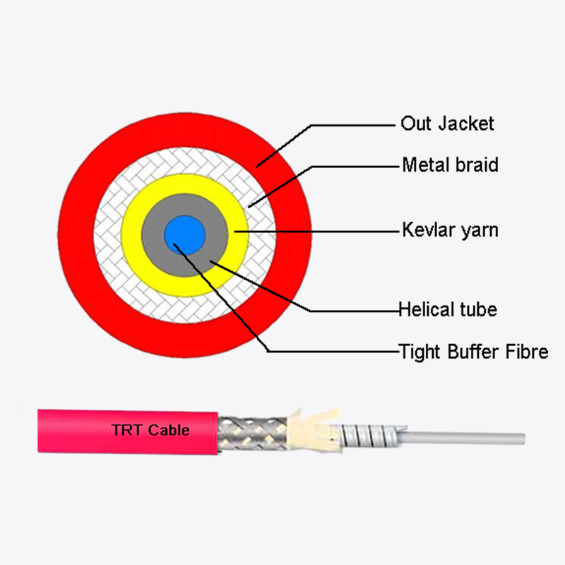
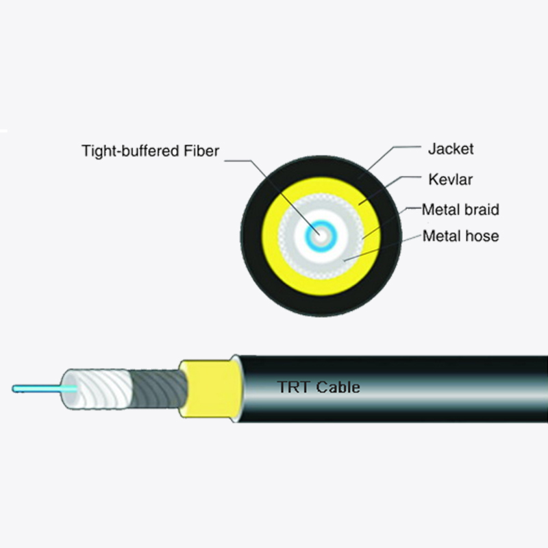
The tight buffer fiber optic cable tbf (gji) is an engineering solution optimized for environments where frequent handling, flexibility, and direct termination are paramount. Its construction is a layered approach, building outwards from the delicate fiber to the final cable jacket.
The process begins with the optical fiber itself, which consists of the glass core and cladding, protected by a thin, soft primary coating. The defining step is the application of the tight buffer. This is a secondary coating, typically 900µm in diameter, that is extruded directly onto the primary coated fiber. This layer is not just a sleeve; it is a bonded, robust plastic layer that provides substantial crush resistance and protects the fiber from microbending losses, which can degrade signal quality.
Multiple tight-buffered fibers are then stranded around a central strength member, which is almost always made of rigid materials like fiberglass or aramid yarn (e.g., Kevlar®). This central strength member is the backbone of the cable; it is the component that absorbs the tensile load during and after installation, preventing any significant strain from reaching the fibers themselves. The arrangement of fibers around this core contributes to the cable’s excellent flexibility and balanced construction.
The assembly is then enclosed in an overall jacket. The material of this jacket is critically selected based on the application. For general indoor use, Polyvinyl Chloride (PVC) is common. For spaces where air circulation is used, such as the plenum spaces above suspended ceilings, a plenum-rated jacket made of low-smoke, zero-halogen (LSZH) material is mandatory for fire safety. Similarly, riser-rated cables are designed for vertical runs between floors, with jacket formulations that resist flame propagation. This makes the tight buffer fiber optic cable tbf (gji) a versatile solution for a wide range of indoor applications.
A Detailed Look at Loose Tube Cable Construction
The loose tube cable is the workhorse of outdoor and harsh environment installations. Its design is fundamentally geared towards surviving the rigors of the external plant, where temperature extremes, moisture, and long-term tensile loading are constant concerns.
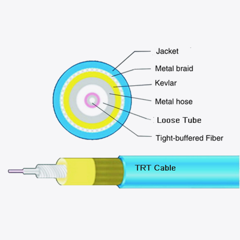
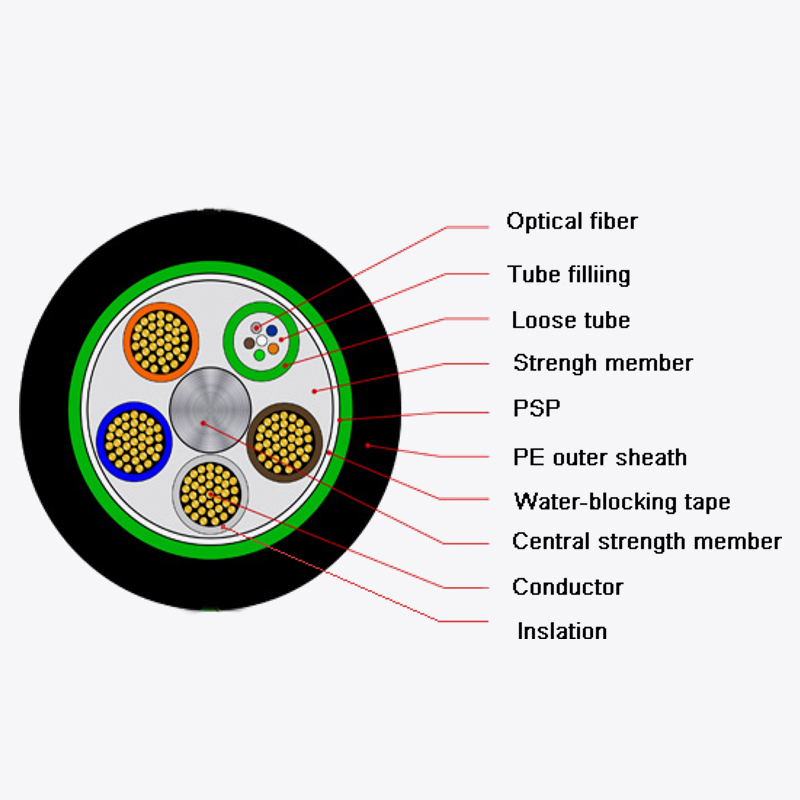
The construction starts similarly, with a bare 250µm coated fiber. However, instead of being tightly coated, one or more of these fibers are placed loosely inside a hard, thermoplastic buffer tube. The internal diameter of this tube is much larger than the fiber itself, creating the essential air gap. To prevent water ingress, these tubes are typically filled with a soft, water-blocking gel. This gel completely surrounds the fibers, blocking any potential path for water to travel along the cable core. Modern designs also employ dry water-blocking technology, which uses super-absorbent powders or tapes, to avoid the mess associated with gel-filled cables, a feature often preferred for indoor-outdoor applications.
Multiple of these buffer tubes are then stranded around a central strength member. In loose tube cables, this central strength member is often made of steel, providing immense tensile strength. The tubes are helically wound around this core, a design that allows the cable to elongate slightly under tension without stretching the fibers inside the tubes. This is the core of the “strain-free” philosophy.
The entire core is then typically surrounded by additional strength members, such as corrugated steel tape, for robust crush resistance and rodent protection. The final outer jacket is made of a tough, polyethylene (PE) material that is resistant to moisture, ultraviolet (UV) radiation, and abrasion, ensuring long-term durability when directly buried, placed in conduit, or strung aerially on poles.
Head-to-Head: A Comparative Analysis of Key Characteristics
To make an informed decision, it is essential to compare the performance of these two designs across several key operational parameters. The following table provides a clear, side-by-side comparison.
| Characteristic | Tight Buffer Cable | Loose Tube Cable |
|---|---|---|
| Primary Application | Indoor, controlled environments (e.g., data centers, LANs, building backbone) | Outdoor, harsh environments (e.g., aerial, direct burial, duct) |
| Core Design Principle | Direct protection; fiber is bonded to a thick secondary coating. | Strain-free; fiber is isolated within a larger, often gel-filled, tube. |
| Flexibility | Excellent. Highly flexible and suitable for tight bends and frequent moves. | Good on a macro scale, but individual fibers are fragile when isolated. |
| Crush Resistance | Very good, due to the thick buffer and tight construction. | Excellent, often enhanced by metallic armoring. |
| Tensile Strength | Moderate. Relies on central and peripheral strength members. | Very high. Designed for pulling and long-term aerial tension. |
| Temperature Tolerance | Moderate (typically -20°C to +70°C). The tight buffer can contract/expand. | Wide (typically -40°C to +85°C). The loose tube design accommodates expansion. |
| Water/Moisture Resistance | Fair. Not inherently water-blocked; relies on jacket integrity. | Excellent. Uses gel-filled or dry-blocked tubes and a moisture-resistant jacket. |
| Termination & Splicing | Easier to terminate directly with connectors; no fan-out kit required. | Requires a “fan-out kit” to build up individual fibers for connectorization. |
| Diameter & Weight | Generally smaller and lighter for a given fiber count. | Larger and heavier due to buffer tubes, gels, and armoring. |
Mechanical and Environmental Performance
The data in the table highlights a clear trade-off. The tight buffer fiber optic cable tbf (gji) excels in mechanical robustness for its intended use case. The 900µm coating provides superior protection against crushing forces and makes the fiber far less susceptible to damage from rough handling during installation within a building. Its flexibility is a key buyer industry search term, as it allows for easier routing through crowded conduits and tight spaces in server racks and patch panels.
Conversely, the loose tube cable is engineered for harsher environmental conditions. Its wide operating temperature range is essential for outdoor use, where cables can be frozen in ice or heated by direct sunlight. The gel-filled tubes provide a complete barrier against moisture, which is the single greatest threat to the long-term reliability of an outdoor fiber optic system. While a tight buffer fiber optic cable tbf (gji) is robust, it is not designed to withstand prolonged exposure to groundwater or the significant contraction forces experienced in sub-zero temperatures.
Installation and Termination Practicalities
This is one of the most significant differentiators from an installer’s perspective. A tight buffer fiber optic cable tbf (gji) is fundamentally easier to work with inside buildings. The individual fibers are already robust enough to be directly handled and terminated with standard connectors. This simplifies the process, reduces installation time, and lowers labor costs. The smaller diameter and lighter weight also make it easier to pull through vertical risers and manage in space-constrained data center overhead trays.
Loose tube cable, while rugged, presents more complexity at the termination point. The bare 250µm fibers within the buffer tubes are extremely delicate and cannot be connectorized directly. Each fiber must be fed through a “fan-out kit”—a small, rigid sleeve that provides the mechanical stability of a 900µm buffer—before a connector can be attached. This adds steps, time, and cost to the installation process. Furthermore, the gel filling, while excellent for water-blocking, can be messy and requires careful cleaning, which is a consideration for buyers evaluating total project cost.
Choosing the Right Cable for the Application
The analysis leads to a clear set of guidelines for selecting the appropriate cable design. The choice is overwhelmingly dictated by the physical environment in which the cable will be deployed.
When to Choose a Tight Buffer Cable
The tight buffer fiber optic cable tbf (gji) is the unequivocal choice for all indoor and controlled environments. Its design attributes align perfectly with the demands of these settings.
Data Center and LAN Applications: Within data centers and local area networks (LANs), cable flexibility and high fiber count in a small diameter are critical. The ability to make tight bends in patch panels and routing pathways without signal loss is a key advantage. The ease of direct termination means that network technicians can quickly deploy and reconfigure connections. The availability of plenum and riser-rated versions ensures compliance with fire codes, a non-negotiable requirement for wholesalers and system integrators to understand.
Equipment Interconnects and Patch Cords: The physical durability of the tight-buffered fiber makes it ideal for use as patch cords, which are frequently handled, plugged, and unplugged. The robust construction resists damage from bending and crushing in crowded cabinet environments.
When to Choose a Loose Tube Cable
The loose tube design is the default solution for the outdoor plant (OSP). Its resilience to environmental factors makes it indispensable for long-haul deployments.
Aerial, Direct Buried, and Duct Applications: For cables strung between telephone poles, buried directly in the ground, or pulled through underground conduits, the loose tube design is mandatory. Its high tensile strength supports aerial spans, its armored core resists rodent attacks and ground pressure when buried, and its water-blocking technology ensures longevity. The gel-filled tubes also prevent water from migrating along the cable length, which could otherwise damage sensitive electronic equipment at either end.
Harsh Industrial Environments: In settings like chemical plants, mining operations, or along railway lines, where exposure to chemicals, oils, and extreme temperatures is likely, the rugged, hermetically sealed nature of a loose tube cable is often required.
The Bridge: Indoor/Outdoor Cables
A modern solution that blurs the line between these two types is the indoor/outdoor cable. This design typically uses a loose tube core, often with dry water-blocking technology, to provide the environmental protection needed for the outdoor run. However, it is then sheathed in a riser-rated or plenum-rated LSZH jacket to meet fire code requirements for the indoor portion. This eliminates the need for a splice at the building entry point, reducing cost and a potential point of failure. For a buyer, this represents a versatile and often cost-effective solution for projects that traverse both environments.
 Address:Zhong'an Road, Puzhuang Town, Suzhou City, Jiangsu Prov., China
 Phone:+86-189 1350 1815
 Tel:+86-512-66392923
 Fax:+86-512-66383830
 Email:[email protected]
 Wechat: xiaobin18913501815
 whatsapp: +86 18913501815
 0
0

 English
 русский
 Español
 Português
 عربى
عربى


